Sunday, November 23, 2014
Wednesday, November 13, 2013
Revit Architecture 2011 View Control Bar, View Cube, Navigation Bar, Ribbon, Tabs,
View Control Bar
The View Control bar is at the bottom of every view and is contextual based on the type of view
that you’re working in . Some views (like sheet views) won’t have them. Perspective
views won’t show a scale.
From left to right you have Scale, Detail Level, Visual Style, Sun Path (on/off), Shadows
(on/off), Rendering Show/Hide (only in 3D views), Crop (on/off), Show Crop (show/hide),
Temporary Hide/Isolate, and Reveal Hidden Elements.
One of the nice features in Revit Architecture 2011 is the ability to see realistic colors from the
visual style.

The difference is subtle, but when combined with other graphic features, it will likely lead to
users not rendering project views that are part of the document set. Rather, they’ll opt for having
real-time views.
View Cube
You’ll find the View Cube in 3D views.

Hovering over the View Cube will reveal the Home option (the little “house” above the
View Cube), which will bring you back to your home view. Right-clicking the View Cube will
open a menu that allows you to set, recall, and orient your view.

Selecting the Options menu will take you directly to the View Cube options in the Options
Bar.

Navigation Bar
The Navigation bar contains the Navigation Wheel, View Zoom, and Pan controls.

Ribbon
The Ribbon contains all of the Revit functionality for designing and documenting your Revit
project . There are specific portions of the Ribbon that you should be familiar.

Tabs
Tabs are used to select from among the various groups of functionality in Revit. There are nine
tabs in the Revit Ribbon.
We’ll take a moment to briefly describe these tabs.
Home The Home tab is used to create or place content (both system and component families)
as well as datum
Insert The Insert tab is used to link external files (2D, 3D, image, and Revit file types) as
well as search for external content via Autodesk Seek.

Annotate The Annotate tab contains many of the tools necessary to annotate, tag, dimension,
or otherwise graphically document your project.
Structure The Structure tab contains the tools necessary to add elements, which can be
structurally analysed in Revit Structure. You can also add datum from this tab.

Massing & Site The Massing & Site tab contains the tools necessary to add massing- and
site-related elements.

Other than infrequency of use, Massing and Site elements are so conceptually dissimilar that
we believe they should occupy separate tabs.
Collaborate The Collaborate tab refers to the tools that you’ll use to coordinate and manage
the project within your own team as well as across other teams and their linked files.

View The View tab refers to the tools that you’ll use to create all your project views, 2D and
3D, as well as schedules, legends, and sheets. You can also modify your user interface from
this tab, including your keyboard shortcuts.
Manage The Manage tab contains all your project standards and other settings. This tab also contains your design option and phase tools. We believe it would
make more conceptual sense to locate design option and phase tools in the Home tab.

One of the most important settings that you’ll use during your project is Object Styles on the
Manage tab. Selecting this option will allow you to manage the global visibility settings for
just about everything in your project: how it projects, how it cuts, and its associated color and
pen weight.
Modify The Modify tab contains the tools you’ll use to manipulate all the content that
you’re creating in your Revit project

Contextual Modify Contextual Modify tabs are contextually revealed as part of an addition
to the Modify tab when specific elements are selected. Contextual tabs are
located to the far right of all the other panels in your Ribbon.

Panels
Panels identify areas of grouped functionality in the Ribbon. They can also be pulled out of tabs
and arranged so that functionality is persistently exposed. To relocate a panel, simply click and
drag the panel portion out of the Ribbon.

The panels will snap together if you hover over a previously placed panel. To return a panel
to the Ribbon, simply click the small down arrow that is in the upper portion of the right grey
bar in the panel set.
Options Bar
The Options Bar is a contextually sensitive area that gives you feedback as you create and modify
content

Revit Architecture 2011 Project Browser, Status Bar, Drawing Area, Working sheet view
Project Browser
The Project Browser is a project tree of all the views, legends, schedules, sheets,
families, groups, and links in your Revit project. You can collapse and expand the project tree by
selecting the + or – icons.

The Project Browser can also be filtered and grouped into folders based on a number of user defined
parameters. To access the type properties of the Project Browser, simply right-click the
Views portion at the top of the palette

Status Bar
The status bar provides useful project information on files that are opening or already open. Project information such as work sets, design options, and filters is immediately
accessible from the status bar.
Drawing Area
The drawing area is the window into your design space. In this example, we’ve tiled four different
view types: plan, elevation, 3D, and sheet view . Rather than jump between
expanded drawing areas that obscure each other, it’s sometimes helpful to tile many views in
the same area.

When you do this, you’ll only be able to zoom into the extents that are defined by the drawing
area. If you want to get around this limitation, here’s a helpful tip.
Create a new sheet, but then delete the sheet (keeping the view). This is your “working” space
for any view of the project. Now you can create duplicate views of any of your project views and
assemble them in this working space . Zooming in and out is much more fluid, and
you’re not limited to the extents of one drawing area. You can create a keyboard shortcut to activate
and deactivate views, which is helpful as well.
Working Sheet View

Tuesday, August 2, 2011
Revit Architecture 2011 Interface,InfoCenter and Properties
Revit Architecture 2011 Interface Organization
InfoCenter
To the far right of the QAT is the InfoCenter.
 From left to right, you have the ability to search, access the Subscription Center, access the
Communication Center, save favorites, and get help.
Properties
The Properties tab contains the instance parameters of whatever you’re currently working on.
From this palette you can access the Type Selector, filter properties, and edit type parameters.

InfoCenter
To the far right of the QAT is the InfoCenter.
Communication Center, save favorites, and get help.
Properties
The Properties tab contains the instance parameters of whatever you’re currently working on.
From this palette you can access the Type Selector, filter properties, and edit type parameters.

Revit Architecture 2011 Interface,Application Button and Quick Access Toolbar
Revit Architecture 2011 Interface Organization
Application Button
The Application button,
 also called the application menu, allows you to access commonly used commands: New, Open, Save, Print, and so on. You can also export your project to a number of 2D and 3D formats from this menu. This is also where you would manage licensing information. The Publish option will allow you to publish RFA files to Autodesk Seek.
Quick Access Toolbar
The Quick Access toolbar (QAT) allows you to create a group of frequently used tools into one selection area.

Right-clicking a command in one of the tabs will allow you to add elements to the QAT
 By clicking the small, down-facing arrow to the far right of the QAT, you’ll find that commands
may be further customized, grouped, and removed from the toolbar.
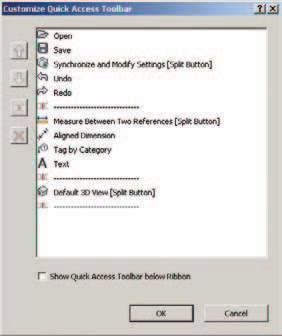 You also have the option to show the QAT below the Ribbon.
Application Button
The Application button,

Quick Access Toolbar
The Quick Access toolbar (QAT) allows you to create a group of frequently used tools into one selection area.
Right-clicking a command in one of the tabs will allow you to add elements to the QAT

may be further customized, grouped, and removed from the toolbar.

Revit 2011 Interface Organization
Interface Organization
As mentioned, the interface has evolved for Revit Architecture 2011 and has improved in a lot of areas. Persistence of command location is the key. So even though functions remain contextually exposed and hidden depending on what you’re working on, the majority of those contextual commands are in the same place.
 shows the Revit 2011 UI. To illustrate some different project views, we’ve tiled four different view windows: Plan, Elevation, 3D, and Sheet.
As mentioned, the interface has evolved for Revit Architecture 2011 and has improved in a lot of areas. Persistence of command location is the key. So even though functions remain contextually exposed and hidden depending on what you’re working on, the majority of those contextual commands are in the same place.

Monday, August 1, 2011
Revit 2011 Project management
Management
Project management has to do with all the project settings that control (and therefore restrict)
any number of project variables. Looking at the Revit organizational chart ,we’ll discuss each of the management options in the rest of the chapter as we discuss the UI.
At the moment, the most important part of project organization to discuss is worksets, because this has to do with workflow and how the team comes together to work on the project simultaneously. Worksharing is covered in more detail, but we’ll cover this topic here at a high level as it relates to overall workflow of Revit.
There are two kinds of worksets: system managed and user managed. The user cannot create, manage, or assign system-managed worksets. Users can only create, manage, and assign worksets and elements that are assigned to user-created worksets.

When worksharing is enabled, Revit creates worksets for everything in the project: datum, content, views, and settings. Revit manages the worksets related to families, views, and project standards.
But as for the actual content that is being used in your project (not just loaded, but actually in use) such as datum, 3D host and system families, and spaces, Revit allows you to create, manage, and assign worksets to those elements. The elements that are assigned to user-defined worksets are illustrated in

Levels and grids are assigned to the Shared Levels And Grids workset. All other 3D project
geometry (system or components) is assigned to Workset1. The great thing is that you only need to create and assign workset to a limited number of things that you’re using in your project. Revit is managing the worksets assigned to everything else.
Sunday, July 31, 2011
Revit 2011 Create 3D Views
There are two kinds of 3D views in Revit: orthographic and perspective. 3D views are orthographic, and Camera and Walkthrough views are in perspective. You can’t change one to another after the fact, so select carefully.
 Orthographic views will always show parallel edges along Cartesian X-, Y-, and Z-axes. Orthographic views are best if you need to show model information to scale. A lot of people don’t realize that it’s possible to dimension and detail in Revit from a 3D orthographic view. After isolating the part of the model that you want to dimension, the trick is to set the appropriate work plane.
 before dimensioning.
As long as you’re careful about setting the work plane as you work, you can add dimensions and text to your views, as shown in
 Create perspective views by placing the start and end points of a camera (typically from a plan view). It should be noted that the first point you select in plan is where the view will be taken from, but the second point is also the rotation origin for the view.
 This is important because if you select a second point that is far beyond your view, when you open the view and attempt to modify it, it will rotate around a target that doesn’t seem to make sense. That’s because the target location of the view is off in the distance. A perspective view will not be to scale, but it can be made relatively larger or smaller by selecting the view’s boundary and then selecting the size crop from the Modify | Camera tab.
 Once you do this, you’ll have the option to change the view size and field of view (proportionally or nonproportionally). You can also simply drag the nodes of the bounding box.
Camera extents are defined by the Far Clip Offset option, accessed in the View Properties’ View Extents settings.
 If the Far Clip Offset is too shallow, the view will look something that.
 Geometry that you’d expect to see will be “clipped” in the view.
Simply increase the Far Clip Offset value to show more of the model. You may also do this graphically by returning to a plan view, right-clicking the view, and selecting Show Camera.
 Once the camera is shown in your plan view, you may select the node at the far end of your clipping plane and manually drag the node to extend the Far Clip Offset of your view.

Finally, 3D views (even walkthroughs) contain section boxes, which become active when selecting the Section Box option.
 This will allow you to control how much of the project is shown and is helpful for creating cutaway visualizations in real time or in renderings.


As long as you’re careful about setting the work plane as you work, you can add dimensions and text to your views, as shown in


Camera extents are defined by the Far Clip Offset option, accessed in the View Properties’ View Extents settings.


Simply increase the Far Clip Offset value to show more of the model. You may also do this graphically by returning to a plan view, right-clicking the view, and selecting Show Camera.


Finally, 3D views (even walkthroughs) contain section boxes, which become active when selecting the Section Box option.

Revit 2011 Creates Legends and Schedules
Legends
There are two types of legends: legends and keynote legends. Regular legends are used to assemble
analytic views of content in your project, graphics, geometry, tags, and so on—anything that lives in
your project. Legends may contain Detail, Repeating Detail, and Legend components.
 A Legend component
 is a special bidirectionally associative representation of 3D system and component families that may only appear in legend views (not drafting views). If the actual thing in your project changes, the representation of that thing in your legend will change as well.
Keynote legends are special schedules. When creating a keynote legend, you’ll be prompted
much the same way as you are when creating a schedule.

Schedules
There are five types of schedules in Revit: Schedule/Quantities, Material Takeoff, Sheet List, Note Block, and View List.
 Schedules/Quantities in Revit are used to quantify the actual building elements that are being used in the project, not the elements that are loaded in the project.

Three categories of elements may be scheduled via Schedules/Quantities:
Documentation
Sheets in Revit ultimately contain all the documentation for your project and will come in a variety of standard as well as custom sizes. The important thing to remember is that you’re not going to select a “scale” when you print a sheet; it’s really more like printing than “plotting.” If you need your sheet to be smaller or fit on the desired page, these options are available and little different than printing from a word processing application.
There are two types of legends: legends and keynote legends. Regular legends are used to assemble
analytic views of content in your project, graphics, geometry, tags, and so on—anything that lives in
your project. Legends may contain Detail, Repeating Detail, and Legend components.


Keynote legends are special schedules. When creating a keynote legend, you’ll be prompted
much the same way as you are when creating a schedule.

Schedules
There are five types of schedules in Revit: Schedule/Quantities, Material Takeoff, Sheet List, Note Block, and View List.


Three categories of elements may be scheduled via Schedules/Quantities:
- Masses: Mass and Mass Floors
- Spaces: Rooms and Areas
- Content: System and component families
Documentation
Sheets in Revit ultimately contain all the documentation for your project and will come in a variety of standard as well as custom sizes. The important thing to remember is that you’re not going to select a “scale” when you print a sheet; it’s really more like printing than “plotting.” If you need your sheet to be smaller or fit on the desired page, these options are available and little different than printing from a word processing application.
Revit 2011 Creates Callouts and Drafting Views
Callouts
There are two types of callouts: Detail and Floor Plan.
 Although Detail callouts may look like Detail sections graphically, they’re not visible inside other perpendicular views. So a callout created in plan view will not be visible in elevations or sections like a Detail section.
It’s probably best to think of a Detail callout as an enlarged view. Its Far Clip settings are by default the same as the parent view.
 You can think of a Floor Plan callout as another plan view but with associated callout graphics. Floor Plan callouts also have all the same view controls as a regular plan view, such as Depth Clipping and View Range.
 Take a moment to note the line and control arrows around the border of the view. By modifying the location of these arrows, you’re modifying the extents of the view. Of course, more than plan views can have their extents modified; elevations, sections, and callouts can all have their view extents modified in the same way.
Drafting Views
Drafting views give you the ability to draw without first creating a reference to something in your project. They may contain Detail and Repeating Detail components, as well as all the annotation and documentation tools that Revit has to offer. Drafting views are great for drafting standard or analytic conditions that don’t require an actual geometric underlay.
And once you’ve created a drafting view, you may refer to this view when creating an elevation, section, detail, and so on that would normally rely on an actual view of the model. As you start to create a standard project view,
 simply select the Reference Other View option and then you’ll be allowed to select a reference view from all the other like views in your project, as well as any drafting views.
There are two types of callouts: Detail and Floor Plan.

It’s probably best to think of a Detail callout as an enlarged view. Its Far Clip settings are by default the same as the parent view.


Drafting Views
Drafting views give you the ability to draw without first creating a reference to something in your project. They may contain Detail and Repeating Detail components, as well as all the annotation and documentation tools that Revit has to offer. Drafting views are great for drafting standard or analytic conditions that don’t require an actual geometric underlay.
And once you’ve created a drafting view, you may refer to this view when creating an elevation, section, detail, and so on that would normally rely on an actual view of the model. As you start to create a standard project view,

Subscribe to:
Posts (Atom)